We help the world growing since 2013
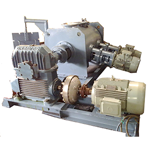
Plough Shear Mixer has a horizontal cylindrical shape with flat end plates. The main shaft passes through the axis of the vessel and is supported at the end plates in specially designed bearing housing. The plough shaped mixing elements are arranged concentrically on the main shaft. The clearance between the ploughs and shell wall is minimum, to facilitate better mixing.
| Model | Working Capacity | HP (Plough Shear) | HP (Chopper) |
|---|---|---|---|
| DSP PSM 100 | 25 - 80 | 3 HP | 1 HP X 1 HP |
| DSP PSM 200 | 60 - 200 | 5 HP | 2 HP X 2 HP |
| DSP PSM 300 | 130 - 300 | 10 HP | 3 HP X 3 HP |
| DSP PSM 500 | 160 - 500 | 15 HP | 5 HP X 5 HP |
| DSP PSM 700 | 250 - 700 | 20 HP | 5 HP X 5 HP |
| DSP PSM 1000 | 400 - 1000 | 25 HP | 7.5 HP X 7.5 HP |
| DSP PSM 1500 | 500 - 1500 | 40 HP | 7.5 HP X 7.5 HP |
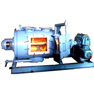
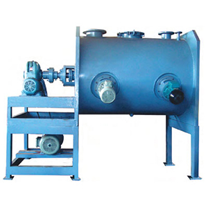
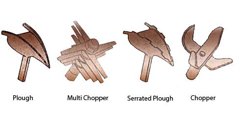
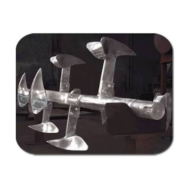
The Mixer consistes of a cylindrical shell, fitted with series of ploughs rotated on the central shaft which incorporates ploughing motion. This pattern results in collisions and blending of both dry and wet materials. Plough Shear Mixer is long term operation for various applications like mixing, grinding, dispersion etc. Multiple Choppers are fitted on the mixing vessel between ploughs. Choppers can be with multiple blades or simple depending on the applications.. They prevent lump formation and better mixing. For controlling the mixing, the Chopper motor can be switched on and off independently.
Generally a feed inlet nozzle is provided at the top of the mixer with quick opening lid Rotary valve, Butterfly valve etc. can be provided depending on application.
Discharge nozzle is provided at the bottom of shell for discharging wet or dry material Operation of Discharge door shall be operated manually. This can be pneumatic or hydraulic depending on application. Besides this one or more Flat type Inspection doors can be fixed, on the front side of the mixer.
Blender can be designed with jacket or without jacket for heading or cooling application.
The Equipment can be designed for pressure and vacuum application where in solid/Liquid/gas phase reaction can be carried out.
Fluid Coupling is fitted in between motor and gear box to prevent shock loading on gear box, prevents the drawing of large current by the motor and damage to the drive elements due to frequent starting and stopping of motor.
On off switching for plough and chopper. Ammeter, Voltmeter, Temperature indicator Pressure indicator Audio Visual Alarm are housed in the panel.